CG-Review List
[[02-GAMES101-Modeling Transformation|Modeling Transformation]]
- What are the transformation matrices in 3D space represented with homogenous coordinate?
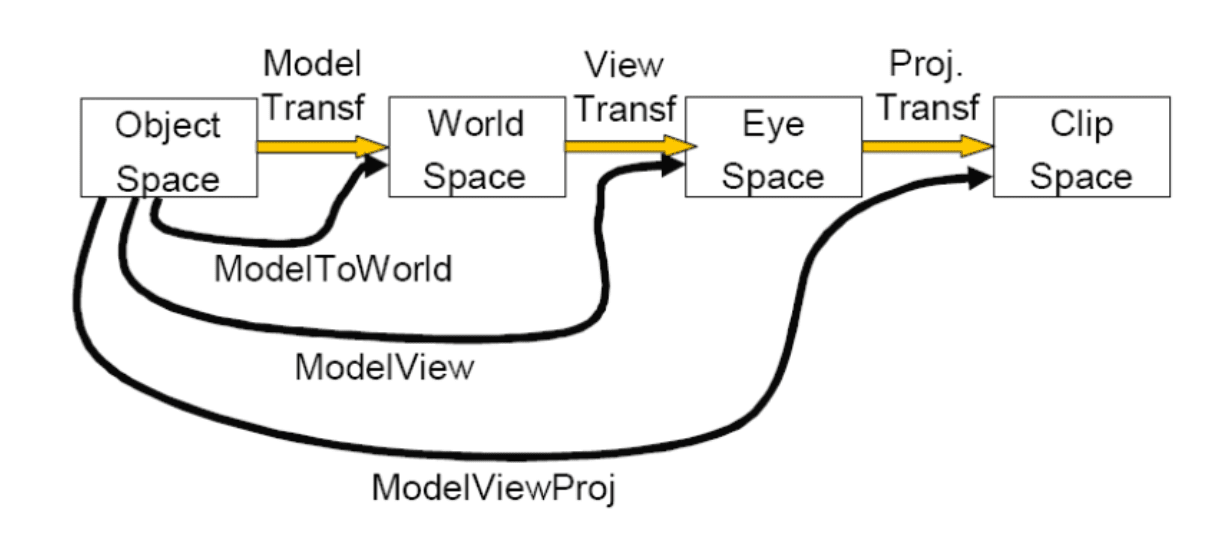
- Transforms objects from local coordinate system (model coordinate system) to the world coordinate system.
- [[02-GAMES101-Modeling Transformation|Modeling Transformation]]
[[03-GAMES101-Viewing Transformation|Viewing Transformation]]
- Transforms objects from the world coordinate system to the view coordinate system (camera coordinate system), simulating the viewpoint of an observer (camera).
- [[03-GAMES101-Viewing Transformation|Viewing Transformation]]
- What are orthogonal projection and perspective projection?
Orthogonal projection
- How can the depth value z be interpolated in screen space?
- By using perspective Projection
Perspective projection
- How can a point in world coordinate system projected to image?
From Object Space to Clip Space
- Specify the projection matrices and calculate the result. Code or algorithm.
- [[02-GAMES101-Modeling Transformation|Modeling Transformation]]
- [[03-GAMES101-Viewing Transformation|Viewing Transformation]]
- Transform a point from World Coordinate to Camera Coordinate
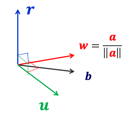
- First, create a coordinate frame for the camera
- Define a rotation matrix
- Apply appropriate translation for camera (eye) location
- First, create a coordinate frame for the camera
- First, create a coordinate frame for the camera
- Define a rotation matrix
are three orthogonal basis vectors that describe the camera coordinate system (view coordinate system).
- They are defined in the world coordinate system and are used to represent the camera's orientation and pose.
- Apply appropriate translation for camera (eye) location
[[05-GAMES101-Shading|Shading]]
5.1 What are the factors in illumination?
- Ambient, Diffuse, Emissive, Specular
- Surface properties
- Reflectance spectrum(color)
- Geometry
- Absorption
- Light sources with:
- Emittance spectrum (color)
- Geometry (position and direction)
- Directional attenuation (falloff)
5.2 How to calculate with equation?
- Single light source (with attenuation):
- Name: Total Illumination
- Meaning: Final light intensity at a surface point (combines ambient, diffuse, and specular components).
- Type: Scalar/Vector (for RGB colors).
- Name: Ambient Reflection Coefficient
- Meaning: Controls how much ambient light the surface reflects (0 = no reflection, 1 = full reflection).
- Name: Ambient Light Intensity
- Meaning: Base intensity of the surrounding ambient light (uniform, directionless).
- Name: Diffuse Reflection Coefficient
- Meaning: Controls diffuse reflection strength (related to surface color, e.g.,
for red).
- Name: Surface Normal Vector
- Meaning: Unit vector perpendicular to the surface (must be normalized for correct calculations).
- Name: Light Direction Vector
- Meaning: Unit vector from the surface point to the light source (e.g.,
).
- Name: Light Source Intensity
- Meaning: Brightness of the light source (often multiplied by an attenuation factor for distance).
- Name: Specular Reflection Coefficient
- Meaning: Controls specular highlight strength (e.g.,
for white highlights on metal).
- Name: Half-Vector (Half-Angle Vector)
- Meaning: Unit vector halfway between
and the view direction :
- Name: View Direction Vector
- Meaning: Unit vector from the surface point to the camera (observer).
- Name: Shininess Exponent
- Meaning: Controls highlight sharpness: larger
= smaller, sharper highlights (e.g., for metal, for plastic).
- Unit Vectors:
must be normalized for correct dot product calculations. - Attenuation: In practice,
is often scaled by a distance-based factor (e.g., ). - Vector Math: For RGB colors, apply the model per color channel (R, G, B).
- Multiple light sources (with attenuation):
- What are flat shading and smooth shading? How to calculate the vertex normal?
- Flat shading: Perform lighting calculations per face, using normal vector to the face.
- Gouraud shading: Perform lighting calculations per vertex, using vertex normals.
- Phong shading: Perform lighting calculations per fragment. Requires interpolating normals.
- Vertex Normal
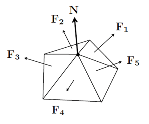
- Vertex Normal
- Gouraud shading:
- Find vertex normals
- Apply modified Phong model at each vertex
- Interpolate vertex shades across each polygon
- Phong shading:
- Find vertex normals
- Interpolate vertex normals across edges
- Interpolate edge normals across polygon
- Apply modified Phong model at each fragment
[[02-CG-Texture Mapping|Texture Mapping]]
7.1 What is texture mapping?
- Adds visual detail to scenes
- Without raising geometric complexity
- A shading trick makes a surface look textured
7.2 How can it be achieved?
Three steps to applying a texture
- Specify the texture
- read or generate image
- assign to texture
- enable texturing
- Assign texture coordinates to vertices
- proper mapping function is left to application
- Specify texture parameters
- wrapping, filtering
7.3 How to get the clamped / repeated texture image in s/t directions? Code or algorithm.
- Clamping
python
def clamping(s,t):
	if (s >1):
		s = 1
	if (t >1):
		t = 1
	if (s <0):
		s =0
	if (t <0):
		t = 0
return s,t- Repeated
python
def repeat(s, t):
    # 对 s 和 t 坐标分别取模 1,实现重复效果
    s = s % 1  # 等效于 s - floor(s),将坐标映射到 [0, 1) 区间
    t = t % 1
    return s, t
7.4 How to obtain the texture mapping for a sphere/cylinder? Code or algorithm.
- Cylindrical Mapping:
- A cylinder can be parameterized using cylindrical coordinates (r, θ, y), where:
- θ is the azimuthal angle (around the cylinder’s axis),
- y is the height along the cylinder’s axis.
- Texture coordinates (s, t) are derived as:
- s = θ / (2π) (maps the circular direction to [0, 1]),
- t = y / height (normalizes the height to [0, 1]).
- Cylindrical Mapping:
cpp
void generateCylinderTextureCoords(GLfloat radius, GLfloat height, int slices, int stacks) {
    GLfloat theta, y;
    GLint i, j;

    for (j = 0; j <= stacks; j++) {
        y = j * height / stacks;
        t = y / height; // Texture coordinate t (vertical)

        for (i = 0; i <= slices; i++) {
            theta = i * 2.0f * M_PI / slices;
            s = theta / (2.0f * M_PI); // Texture coordinate s (circular)

            // Vertex position (x, y, z) on cylinder
            GLfloat x = radius * cos(theta);
            GLfloat z = radius * sin(theta);

            // Assign texture coordinates and vertex
            glTexCoord2f(s, t);
            glVertex3f(x, y, z);
        }
    }
}- Sphere Mapping:
- A sphere can be parameterized using spherical coordinates
(ρ, θ, φ), where:θis the azimuthal angle (longitude, around the equator),φis the polar angle (latitude, from the north pole to the south pole).
Texture coordinates(s, t)are derived as:s = θ / (2π)(longitude → horizontal texture coordinate),t = 1 - (φ / π)(latitude → vertical texture coordinate, inverted to match texture origin).
- Sphere Mapping:
cpp
void generateSphereTextureCoords(GLfloat radius, int slices, int stacks) {
    GLfloat theta, phi;
    GLint i, j;

    for (j = 0; j <= stacks; j++) {
        phi = j * M_PI / stacks; // Polar angle (0 to π)
        t = 1.0f - (phi / M_PI); // Invert to match texture top-down (t=0 at south pole, t=1 at north pole)

        for (i = 0; i <= slices; i++) {
            theta = i * 2.0f * M_PI / slices; // Azimuthal angle (0 to 2π)
            s = theta / (2.0f * M_PI); // Texture coordinate s

            // Vertex position (x, y, z) on sphere
            GLfloat x = radius * sin(phi) * cos(theta);
            GLfloat y = radius * cos(phi);
            GLfloat z = radius * sin(phi) * sin(theta);

            glTexCoord2f(s, t);
            glVertex3f(x, y, z);
        }
    }
}
[[03-CG-Curves|Curves]]
- How to form a Bezier / BSpline curve?
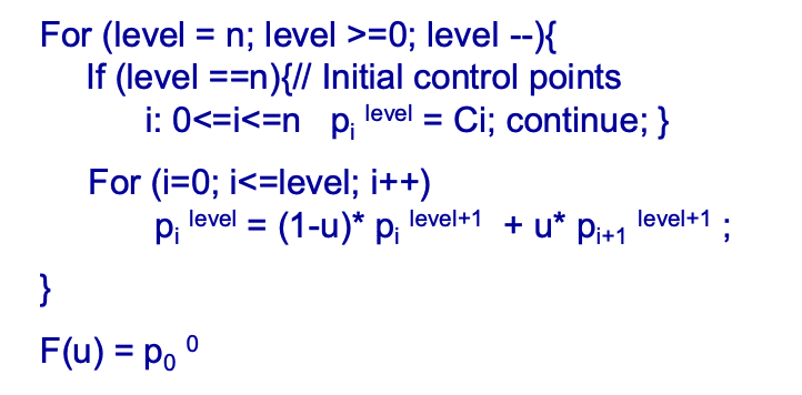
Bernstein-Bezier polynomial basis
- Linear combination of basis functions: Bezier curves are expressed as a linear combination of Bernstein
- Bezier polynomials. For a curve of degree
, it is given by - where
are the control points that influence the shape of the curve, is the parameter, and $$B_{k}^{n}(u)=\frac{n!}{k!(n - k)!}(1 - u)^{n - k}u^{k}$$ are the Bernstein - Bezier polynomials.
[[05-CG-Rasterization|Rasterization]]
- How to rasterize a line? Code or algorithm.
Start point
CODE
cpp
void BresenhamLine(int x0, int y0, int xn, int yn) {
    int dx, dy, incrE, incrNE, d, x, y;
    dx = xn - x0;       // x方向总增量(假设xn > x0)
    dy = yn - y0;       // y方向总增量(正斜率时dy > 0)
    d = 2*dy - dx;      // 初始决策变量d0 = 2Δy - Δx
    incrE = 2*dy;       // 选择E像素时d的增量(2Δy)
    incrNE = 2*dy - 2*dx; // 选择NE像素时d的增量(2Δy - 2Δx)
    x = x0; y = y0;     // 初始化当前像素为起点
    DrawPixel(x, y);    // 绘制起点
    while (x < xn) {    // 逐列扫描,x从起点到终点
        if (d <= 0) {   // 若d≤0,直线在中点M下方或经过M,选E像素
            d += incrE; // d更新为d + 2Δy
            x++;        // 右移一列(y不变)
        } else {        // 若d>0,直线在中点M上方,选NE像素
            d += incrNE; // d更新为d + 2Δy - 2Δx
            x++; y++;   // 右移一列且上移一行
        }
        DrawPixel(x, y); // 绘制当前像素
    }
}
[[06-CG-Raycasting|Raycasting]]
- How to get the intersection between a ray and an object such as a plane or a sphere?
Ray Plane Intersection
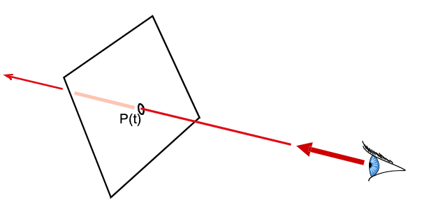
Ray Plane Intersection
- Explicit ray:
- Implicit Plane:
- Intersection Satisfy both:
Ray Triangle Intersection
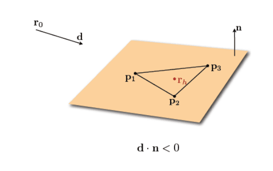
Ray Triangle Intersection
Ray Sphere Intersection
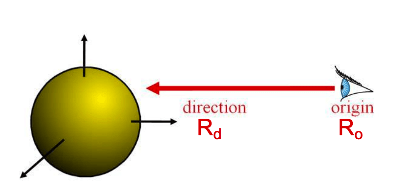
Ray Sphere Intersection
Explicit Ray:
Implicit Sphere
Insert explicit equation of ray into implicit equation of sphere & solve for
Ray Sphere Intersection
Quadratic:
(remember, )
With discriminant:
And solutions:
- What is hidden surface removal? How can it be achieved in CG?
- Hidden surface removal, also referred to as the "visibility problem" in modern terms, is the process of determining which parts of a 3D scene are visible from a specific viewpoint and eliminating the invisible (hidden) surfaces from rendering.
- This ensures that only the correct front-facing or closest surfaces are displayed, creating a realistic sense of depth in computer graphics.
In computer graphics (CG), hidden surface removal can be achieved through several techniques, often integrated into the rendering pipeline:
- Clipping Techniques: Clipping planes (e.g., near, far, left, right, top, bottom planes in a camera’s view frustum) are used to discard objects or parts of objects that lie outside the visible region. This reduces unnecessary computations and directly removes hidden geometry early in the pipeline
- Rasterization-Based Methods: Rasterization algorithms, such as the z-buffer (depth buffer) algorithm, track the depth (z-coordinate) of each pixel during rendering. For each pixel, the algorithm compares the depth of the current surface with the depth stored in the z-buffer and updates the buffer only if the new surface is closer (i.e., has a smaller z-value). This efficiently resolves visibility by ensuring only the closest surface at each pixel is displayed. While the reference materials do not explicitly name the z-buffer, rasterization is listed as a major rendering algorithm tied to visibility solving.
- Ray Casting/Ray Tracing: Ray casting involves shooting rays from the camera through each pixel into the scene and determining the first object each ray intersects. This object is then rendered at that pixel, inherently solving visibility since only the closest intersection is considered. Ray tracing extends this by simulating light reflection and refraction, but the core principle of determining visibility via ray intersections remains central.
- Homogeneous Coordinates and Projection: Using 4D homogeneous coordinates in the projection pipeline preserves 3D depth information (z-coordinates) through transformations, which is critical for hidden surface removal and shading. This allows the pipeline to accurately compare depths during rasterization or other visibility algorithms.